This specification is based on the standard DIN 94 which covers split pins / cotter pins. A comprehensive range of sizes are available Westfield Fasteners.
Cotter Pins, also known as Split Pins are a simple non threaded fastener designed to be inserted into an open ended hole and secured by bending the two tines outward. They are commonly made from wire of semi-circular cross section and square cut at the ends; other specialist end finishes include mitre or bevel shapes. Lengths are measured from the end of the tines/legs to the point where the base of the eyelet hole contacts with the host material. An unthreaded fastener solution designed for single use, as bending fatigue will cause failure if re-used continually.
DIN 94 specifies the permissible form together with dimensions and tolerances for diameters from 0.6 mm up to and including 20 mm diameter. See figure 1 and table 1 for this information. Table 2 shows the tolerances on the shank length.
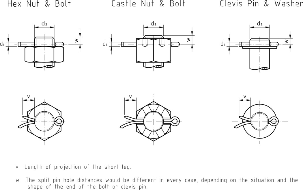
Cotter pins are generally used in conjunction with clevis pins or bolts featuring a transverse hole. Figure 2 and table 3 offer some guidance on appropriate sizes to use with different bolt and clevis pin diameters.
As a general note on diameters, cotter pins are designed to be employed in holes diameters that match the cotter pin's nominal diameter. Cotter pin diameters are toleranced to allow for a measure of clearance, and are therefore designed to be undersize. Please see table 1 for this data.
The shape of the ends of the tines can vary at the manufacturers discretion.
d1 | a | b | c | ||||
---|---|---|---|---|---|---|---|
Nominal Size | Max | Min | Max | Min | = | Min | Max |
0.6 | 0.5 | 0.4 | 1.6 | 0.8 | 2 | 0.9 | 1 |
0.8 | 0.7 | 0.6 | 1.6 | 0.8 | 2.4 | 1.2 | 1.4 |
1 | 0.9 | 0.8 | 1.6 | 0.8 | 3 | 1.6 | 1.8 |
1.2 | 1 | 0.9 | 2.5 | 1.25 | 3 | 1.7 | 2 |
1.6 | 1.4 | 1.3 | 2.5 | 1.25 | 3.2 | 2.4 | 2.8 |
2 | 1.8 | 1.7 | 2.5 | 1.25 | 4 | 3.2 | 3.6 |
2.5 | 2.3 | 2.1 | 2.5 | 1.25 | 5 | 4 | 4.6 |
3.2 | 2.9 | 2.7 | 3.2 | 1.6 | 6.4 | 5.1 | 5.8 |
4 | 3.7 | 3.5 | 4 | 2 | 8 | 6.5 | 7.4 |
5 | 4.6 | 4.4 | 4 | 2 | 10 | 8 | 9.2 |
6.3 | 5.9 | 5.7 | 4 | 2 | 12.6 | 10.3 | 11.8 |
8 | 7.5 | 7.3 | 4 | 2 | 16 | 13.1 | 15 |
10 | 9.5 | 9.3 | 6.3 | 3.2 | 20 | 16.6 | 19 |
13 | 12.4 | 12.1 | 6.3 | 3.2 | 26 | 21.7 | 24.8 |
16 | 15.4 | 15.1 | 6.3 | 3.2 | 26 | 21.7 | 24.8 |
20 | 19.3 | 19 | 6.3 | 3.2 | 40 | 33.8 | 38.6 |
Nominal Length (mm) | +/- (mm) |
---|---|
4-6 | 0.6 |
8-10 | 0.75 |
12-18 | 0.9 |
20-28 | 1.0 |
32-50 | 1.25 |
56-80 | 1.5 |
90-112 | 1.75 |
125-180 | 2.0 |
200-250 | 2.3 |
280 | 2.6 |
Nominal Diameter, d1 | 0.6 | 0.8 | 1 | 1.2 | 1.6 | 2 | 2.5 | 3.2 | 4 | 5 | 6.3 | 8 | 10 | 13 | 16 | 20 | ||
---|---|---|---|---|---|---|---|---|---|---|---|---|---|---|---|---|---|---|
For Diameter Range, d2 | Bolts | over | - | 2.5 | 3.5 | 4.5 | 5.5 | 7 | 9 | 11 | 14 | 20 | 27 | 39 | 56 | 80 | 120 | 170 |
up to | 2.5 | 3.5 | 4.5 | 5.5 | 7 | 9 | 11 | 14 | 20 | 27 | 39 | 56 | 80 | 120 | 170 | - | ||
Clevis Pins | over | - | 2 | 3 | 4 | 5 | 6 | 8 | 9 | 12 | 17 | 23 | 29 | 44 | 69 | 110 | 160 | |
up to | 2 | 3 | 4 | 5 | 6 | 8 | 9 | 12 | 17 | 23 | 29 | 44 | 69 | 110 | 160 | - | ||
v | min | 3 | 3 | 4 | 5 | 5 | 6 | 6 | 8 | 8 | 10 | 12 | 14 | 16 | 20 | 25 | 32 |